Frequently Asked Questions: Inseis
Coloured Inversion (CI)
Inversion Selecting a well limited to very specific wells
I noticed that whenever I open Seismic Inversion, the wells that I can use for estimating the CI operator or for log seis matching is limited to very specific wells (in the project we are currently working on…1 well). I have a well that is just outside the survey area I would like to at least try….is that forbidden?
And does it only look for very specific logs? Without a lot of log aliasing? I have a well with DTCO that doesn’t appear in the list of available wells. I would imagine that with Gardners, you would have everything you need.
Answer
KSI filters the wells that are turned on in the project tree when KSI is launched. The wells it will display in the list must have at least one sonic or velocity log (and a local T-D chart is required to be able to use it – shared T-D charts aren’t supported).
KSI looks for logs classified as “Sonic” or “Velocity” under “Logs > Digital Log Curve Management”, so check there that the DTCO log is classified as type “Sonic”. If it is, ensure the well is turned on in the project tree, then hit “Project > Save Project” before launching KSI. The “Save” operation ensures the database on disk is the same that is in memory – sometimes they get out of sync as database transactions are cached for efficiency.
KSI doesn’t support log aliasing at the moment.
KSI will not let you use a well that is outside the survey area, but you could duplicate the well and logs and move it into the survey area – keep it at least 10 traces inside the survey area though just in case.
Note that when the data is zero-phased, it’s fine to move your wells to the seismic area, in this case you manually set phase rotation=-90 deg
If the well is moved, and the phase of data is unknown, the estimated phase of the operator will be incorrect because the algorithm relies on correlation between seismic and well logs. In this case the operator is unusable, unless you know the phase of the data.
Simulated Annealing (SA)
How to Change depth units from meters to feet
Question
I am wondering how to change the depth units from meters to feet in the displays for looking at the time depth curves, drift, etc.
I am also wondering how to make sure that the program is using feet when I use the log as the macromodel. The documentation says that the meters/feet parameter setting in the inversion parameters is ignored when you use the log as the macromodel.
The units are set as feet in Kingdom.
Answer
The ANSI standard units for absolute impedance are metric, so by default the software displays depth units in metres, and assumes sonic log units are microseconds/foot & density logs are gram/cc, and velocities are in metres/second, and converts to metric for display.
However, you can specify the display units using the “Log Display Options” menu as follows:
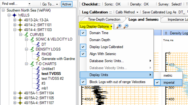
If the sonic logs are not us/f, you can also change those in this menu.
If you use the macromodel from the log, it should match the impedance log quite closely (unless the density isn’t g/cc, in which case you will need to scale the density using the main Kingdom Logs > Log Calculator menu to g/cc, then re-import the scaled density). If the modified macromodel bands are about by a factor of about three, there is probably a metres/feet scaling issue with the sonic log units.
The macromodel parameters units option is for seismic volumes only, which could be metre/s or ft/s (unfortunately Kingdom isn’t very good at recording units in the project).
Can we use the data that has sample rate less than 2 ms?
Can we use the data that has sample rate less than 2 ms? A user is trying to use resampled seismic data (resampled to 1ms) and gets the following error:
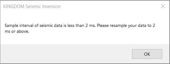
There are 3 reasons why KSI limits the sample rate to be above 2 ms:-
- The max frequency of seismic data people are working with is less than 100 Hz, so it is even sufficient and justifiable to use 4 ms sample interval without losing resolution.
- The length of wavelet in SA is fixed to contain 63 samples. If the data is sampled by 1ms, the wavelet is just 63 ms long which is not long enough to capture the whole shape of the wavelet.
- The run-time will be doubled in inversion if 1 ms is used instead of 2 ms.
We recommend the users to resample their data to at least 2ms for inversion.
Pre-stack Inversion (PSI)
How long will it take to perform inversion and transform on a typical 1000 square kilometers of seismic data in an area of interest… with say 12 cores of processor and 32 GB RAM)?
Bin size: 25 X 25 m
Total traces 1.6 m
Inversion window 1 seconds
12 CPUs
AI inversion: 11 hours
SI inversion 11 hours
Transform 2-3 hours
If you have 24 cores, the run-time will be reduced significantly, but not exactly halved.
What are the data requirements for Prestack Inversion?
For Prestack inversion, following data are required:-
- Seismic data: a minimum of 3 angle stacks or intercept and gradient stacks
- Log data: DT, SDT. RHOB and check-shots are minimum requirement; other logs may help such as GR, SW, VSH, porosity, etc
- Interpretated horizons
- Seismic stacking velocity
For AI – Optimal Chi angle is 0 and correlation of 1 (Positive). Is this because this is perfect data, or is this always the case?
Analytically, i.e. in the EEI math formulation, when chi=0, EEI = AI. Our module has numerically proved it Is true hence correlation = 1
Vp/Vs, Poisson’s Ratio, Lambda*Rho (This prediction almost exact) (all Positive) Is this because this is perfect data, or is this always the case?
The above parameters Vp/Vs etc is non-linearly related to EEI; in other words Vp/Vs can be obtained from EEI with a CHI angle. We expect a very high correlation from log data. However when we estimate Vp/VS from EEI from seismic data, the estimated optimum chi has a small range hence small errors are expected
In the Pre-Stack Data Analysis tab if you only have A + B Stacks and EEI, what can you do with the EEI Reflectivity volume that is generated? Can it be used in the Elastic Parameter Transforms tab? If so, how is it selected as an input?
EEI reflectivity is just a by-product; it will not be inverted, and reflectivity volumes cannot be used for transforms.
What is the physical meaning of the chi angle?
To solve this elastic impedance limitation on incidence angle range, EEI is presented to substitute sinθ x sinθ by tan (chi) in the two-term linearized Zoeppritz equation. EEI can be applied at different χ values to be approximately proportional to elastic parameters such as acoustic impedance, shear impedance, bulk modulus, shear modulus, Lame parameter, and VP/VS ratio.
If we don't have all the well logs that you mentioned, such as shear-sonic logs, will we still be able to do Pre-stack inversion?
You can predict shear logs using Kingdom. Please contact Kingdom customer support fo further details.
Are the incidence angles used to do angle stacks calculated in the inversion module?
Our module uses angle stacks. Hence the angles are already known, for example at: 10, 20 and 30 degrees. There is no need to calculate angles in our module and you can note that gathers are not used in Kingdom Seismic Inversion.
Do inverted volumes need to be exported to see in 2d3dpak/Earthpak or are they immediately available?
One of the advantages of Kingdom Seismic Inversion is that the inverted volumes are immediately available to display in Kingdom, with the software simply requiring Kingdom to be closed and reopened for it to be visible in the tree.
HiDef for Inversion
How to Generate a Macromodel for Kingdom Seismic Inversion
To generate a robust inversion a low frequency background model is required, referred to as the “MACROMODEL” in the surveys tree within the Inversion tool.
This macromodel provides the low frequency component for the seismic traces inverted to absolute impedances, and also provides a constraint on the inversion process to ensure unexpected impedance values aren’t generated. A good macromodel also helps the inversion process run faster.
To generate the macromodel, the inversion “HiDef” tool is used. Essentially it is a 2-pass procedure:
- Start inversion, select the data & run the HiDef tool to generate a macromodel volume. Close the HiDef tool, and Inversion will transfer the HiDef volume into the Kingdom project database.
- Close then re-open the Kingdom project to inspect the macromodel volume in the main Kingdom environment using the usual visualisation tool for vertical sections etc. When you re-start inversion, the macromodel you just generated will be available for use. There is no need to revisit the HiDef tool again.
A more detailed walkthrough is given under “Inversion > Help > Users Guide > The Inversion HiDef Tool”, but the broad workflow is as follows:
First pass: generate the macromodel using the HiDef tool
Launch inversion
Select Wells
For each well you wish to use, select the sonic, density (or generate with Gardner) and T-D chart
Each well opens in a new tab; to add the well to the HiDef tool, click the “In HiDef” button after reviewing the calibrated sonic log.
Open the “HiDef” tab.
Select survey velocity volume
This is the velocity volume you need to add log level detail too – it is assumed to be an interval velocity volume (not average velocity).
Under the “Surveys” folder in the model tree, open the 3d survey and then the “Model For HiDef” folder. Select the velocity volume, and select “Yes” to export the volume (unless you have already exported this volume). The file is exported to a SEG Y file on disk called “model_for_hidef.sgy”.
Select Grids defining the top and base of the layer you wish to invert
Grids provide the boundaries between which log value propagation in the volume will occur. Ensure the grids are all created with the same cell size, and that there are no vertical cross-overs between surfaces (use the clipping option in the “Tools > Math on Two Maps” calculator).
In the Grids folder, select the grids in stratigraphic order, shallowest to deepest. Just use the “Cut from Top” option – the spreading type can be changed in the main HiDef tool.
After selecting the last grid, press the green “Finished” button.
Run HiDef
The “Run HiDef” button should be enabled as all the data is now ready. Press it to launch the HiDef tool.
It may take a few moments for the HiDef tool to launch, but a popup will appear “Do you wish to add a background model velocity in a SEG Y file?”. Click “Yes” and choose the file “model_for_hidef.sgy”. Add 2d SEGY files if you have them and allow the software to do any indexing required.
Work through the HiDef parameterisation and generation. The output file will (by default) be called “model_for_hidef HiDef Smooth Instantaneous.sgy” though you can change it to something more meaningful.
Once the volume has been generated, you can close HiDef.
The inversion window will prompt you for a SEG Y file; select “model_for_hidef HiDef Smooth Instantaneous.sgy” (or whatever you called it). This will be loaded into the Kingdom project database as a new data type. A popup is given to restart the software. Close inversion, then close & re-open the Kingdom project.
Verify the HiDef velocity datatype looks good on vertical seismic displays/VuPAK. You may need to adjust the default color bars. It may be useful to rename the volume to something more memorable, such as “Macromodel for inversion”!
Second pass: use the macromodel in the inversion
Launch inversion and select the well data as before.
Under surveys, open the “Amplitudes” folder & select the seismic data type you wish to invert.
Ignore the HiDef folder, then under “Macromodel” select the volume generated above (if you didn’t rename the volume, it will be “model_for_hidef HiDef Smooth Instantaneous.sgy”).
You can then step through the inversion workflow (LogSeisMatch, Wavelet Estimation, Seismic Scaling and inversion parameter fine tuning) as before, but the final result will be much improved compared to using the well log as the low-frequency component.